Download PDF Speedframe range brochures
Download PDF Speedframe assembly
Innovative Modular Framing Systems
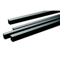
When custom-ordering interior design and architecture products, follow this set of instructions regarding the design and installation of your Speedframe system. Speedframe can supply cut to length tubing and in a flat pack style package ready to be installed on site.Guide Steps:
1. Sketching the unit
Make a simple sketch of the unit to be built.Show tube lengths and joint numbers. (To calculate overall dimensions add 1.6mm to tube length for each insert and 25.4mm for each joint).
Beside the sketch make a list of materials needed-tube lengths, joints, inserts, shelf supports, shelving material etc..referring to the Speedframe Components Guide.
Square Tube Joints
4 off 800mm = 3200mm
4 off 500mm = 2000mm
4 off 450mm = 1800mm
4 off 150mm = 600mm
Total = 7600mm
Joints
4 off 4.1 (1pkt)
4 off 5.2 (1pkt)
Accessories
28 off inserts
4 off Adjustable feet
[/col]
2. Design Rules
Load-bearing capacity depends on design of structure: for instance, a cube of Speedframe is much stronger than a structure with long legs. Avoid continuous spans of more than 1829mm. The following table can be used as a guide to safe beam loadings.
Alloy Speedframe
Alloy system takes approximately 1/3 steel beam loads.
Intercepted members must never be load-bearing unless they are supported by a downward strut (Figure 3). When calculating lengths of intercepted members allow for size of joint and inserts (Figure 4).
When designing with slotted tubes, always work in 25.4mm modules. When cutting slotted tubes, always cut midway between slots.
To strengthen legs of structures, always fit base not more than 152mm above the ground. When building trolleys, either fit base ties at the bottom and use plate-fitting castors or fit reinforced leg units and use 102mm diameter plug-fitting castors. When fitted in this way, these castors are suitable for industrial use and will carry loads of up to 68 kg per castor.
3. Cutting
If not using ready-cut lengths, cut tube to size using a hacksaw and a Speedrame trimming block. (The block should be screwed down to a firm working surface). For maximum economy, cut longest lengths first. Carefully remove burrs from cut ends of the tube using a file.
4. Making Joints
Push insert into open end of tube. Use hard inserts for rigid structures, soft white inserts for structures to be frequently dismantled and rebuilt. Select the joint required and push the arm of the joint into end of tube.(If using single or double shelf supports these should be sandwiched between joint and insert at this stage). Strike the head of the joint (not the arms) with the white face of the Speedframe hammer to drive the joint home — the insert will then retain it firmly in place. Avoid hammering open ends of tube – interpose a piece of wood. Speedframe frameworks can be dismantled by knocking apart with the Speedframe hammer.
Speedframe joints likely to suffer severe vibration or pull-out loads should be permanently fixed by pinning the joint using a self tapping screw. Drill hole about 10mm from edge of tube.
IMPORTANT: Failure to properly apply the design and assembly instructions contained herein may result in you building an unsafe structure. If in any doubt whatsoever, contact your local Speedframe centre for advice before proceeding.


